This is part of the VMware vSAN guide post series. By using the following link, you can access and explore more objectives from the VMware vSAN study guide.
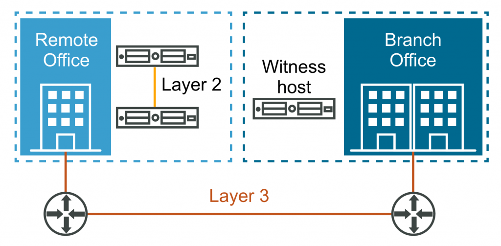
A 2-node vSAN cluster is a configuration where you can create a highly available and fault-tolerant storage infrastructure using just two physical hosts. This setup is ideal for small to medium-sized businesses or remote office/branch office (ROBO) environments that may have limited resources but still require the benefits of vSAN.
As I mentioned in this post, the 2-node vSAN cluster requires two ESXi hosts in the cluster and a vSAN Witness which can be deployed as a virtual machine or on a hardware appliance. I will utilize the virtual appliance to achieve this goal because the vSAN Witness Appliance offers easy maintenance and patching capabilities through vSphere Lifecycle Manager, similar to ESXi hosts. It’s crucial to ensure that the environment fulfills all the necessary requirements for this type of vSAN deployment.
For the purpose of this demo, I am utilizing the following configuration to establish a small environment. This setup will allow me to demonstrate the steps involved in setting up and configuring a 2-node vSAN cluster, as depicted in the following diagram.
This is not officially supported by VMware, as vSAN ESA is only officially supported when using vSAN Ready Nodes.
- 2 nested ESXi hosts (VMware ESXi, 8.0.0, 21203435)
- Each host has a total of 8 network adapters
- 2 network adapters for the management network
- 2 network adapters for the production network
- 2 network adapters for the vMotion network
- 2 network adapters for the vSAN network
- Each host has 1 NVMe hard disk with a capacity of 100 GB for the ESXi itself
- Each host has 1 NVMe hard disk with a capacity of 300 GB for the vSAN datastore
- Each host is powered by an 8-core CPU
- Each host has a total of 24 GB of memory
- Each host has a total of 8 network adapters
- A vSAN Witness appliance
- 1 network adapter for the management network
- 1 network adapter for the vSAN network

I will begin by deploying the vSAN Witness Appliance, followed by configuring a 2-node vSAN cluster, After that, will simulate host and witness failures to test the resiliency of this configuration.
Deploying a vSAN Witness Appliance
1- Download the appliance from the VMware website(I want to deploy vSAN ESA, so I select ESA version).

2- Right-click on a data center, cluster, or host, and select Deploy OVF Template.
3- Specify the location of the vSAN Witness Appliance and click Next.
4- Enter a unique name for the virtual machine, select a deployment location, and click Next.
5- Select a cluster or host to run the vSAN Witness Appliance and click Next.
6- Verify the vSAN Witness Appliance details and click Next.
7- Select a deployment configuration and click Next.
8- Select the disk format for the vSAN Witness Appliance and then select a datastore and click Next.
The following GIF demonstrates all of these steps.

9- Select destination networks for the management network and Secondary Network and Click Next.
10- Set a root password and network properties including vSAN network and management network configuration such as IP address, Gateway, and DNS. and click Next.
By default, the secondary network is chosen for vSAN traffic, but you have the option to change it.
11- Review the page and click Finish. It may take some time for the virtual machine to be deployed.

12- After the deployment is finished, power on the virtual appliance to initiate the initialization process, which may take a few minutes to complete. As you can see, there are two IPv4 addresses: one for management and the other for vSAN traffic.

13- Add the appliance to vCenter Server as a witness ESXi host, please use the management address.

Make sure the vSAN Witness appliance has two VMkernel interfaces (Management and vSAN).

Now vSAN Wintess appliance is ready! let’s configure cluster.
One vSAN Wintess appliance can be shared across a maximum of 64 2-node clusters, supporting up to 64, 000 components, and requires at least 6 CPUs, and 32GB memory allocation for the Witness.
Configure a Two-Node Cluster
1- In the vSphere Client home page, right-click the data center and select New Cluster.
2- Enter a name for the cluster and enable DRS, vSphere HA, and vSAN cluster features.
3- Select the Manage all hosts in the cluster with a single image check box to create a cluster that manages with a single image and Click Next.
4- Set up the desired image and click Next.
5- Review the cluster details and click Finish.
The following GIF demonstrates all of these steps.

6- The cluster will appear in the vCenter Server inventory and show the Quickstart workflow. You can use the Quickstart workflow to quickly configure a cluster. Under Add hosts card click on ADD to open Add hosts wizard.

8- You have two options: entering information for new hosts or selecting from the existing hosts listed in the inventory. Since I have already added hosts to vCenter, I select the Existing hosts option and click Next.
9- Verify the host settings and click Next and then click Finish on the next page.
11- A quick and comprehensive test will be conducted, and if any issues are found, they will be displayed here. I have received some warnings, however, since this is a nested lab environment, these warnings are not a significant concern as they are no errors. On the Configure cluster card, click Configure to open the cluster configuration wizard.

In the first step, you are required to configure the network settings, which involve setting up distributed switches, port groups, and physical adapters. You have two options: either create new distributed switches or utilize existing ones.
Referring to the diagram I shared previously, I have already created a distributed switch specifically for this purpose, following the provided topology. I didn’t use VLANs in this setup, instead, I have physically separated each port group and uplink to ensure isolation and maintain distinct network segments.

12- I click Use Existing to select the existing distributed switch and then select the corresponding distributed port groups for the vMotion network and vSAN network. It’s important to remember that the quick configuration only allows the configuration of vMotion and vSAN traffic. In order to allocate the network adapters correctly, I decided to leave the first four network adapters untouched and assigned the remaining four network adapters to the distributed switch, as shown in the GIF, and click Next.
This mapping to the distributed switches is applied to all hosts in the cluster.
13- On this page, you configure IP address information for vMotion traffic, you can enter the IP address manually for the first host, and then utilize the AutoFill feature to automatically populate the information for the second host or type it manually and click Next.

14 – On the Storage traffic page, configure IP address information for Storage traffic, you can enter the IP address manually for the first host, and then utilize the AutoFill feature to automatically populate the information for the second host or type it manually and click Next.

15- On the Advanced Options page, enter information for cluster settings, including DRS, HA, vSAN, host options, and EVC. I accept the default configuration, except in the vSAN options section, where I select Two node vSAN cluster as the deployment type and click Next.

16- On the Claim disks page, select storage devices to create the vSAN datastore. If you are using verified and compatible disks, you can enable I want vSAN to manage the disks. Otherwise, you should select manually. I mentioned in the previous post, that you need at least 4 NVMe disks, but in my lab, I only use one. Although a warning is displayed, I ignore it and select the first NVMe 300 GB disk anc click Next. As you can see, the total claimed space is 600 GB.

17- Choose the host that you have added to the vCenter inventory to act as a witness host, and then click Next. On the Review page, review the cluster settings, and once you’re satisfied, click Finish.

vSAN has been completely configured, is now up and running, and is ready to host virtual machines. Consequently, we can proceed to create a new virtual machine and select the vSAN datastore as the storage solution. This will allow us to explore the object layout on vSAN for further examination.
After creating a Linux virtual machine with a single hard disk, I navigated to the vSAN cluster and clicked on the Monitor tab. Within the vSAN section, I selected Virtual Objects to access the corresponding virtual objects within the vSAN cluster. It is important to note that there are a total of three objects associated with this particular virtual machine as shown in the following GIF.
- Hard Disk 1: This virtual machine disk stores the contents of the virtual machine’s hard disk drives.
- Virtual Machine Swap Object 1: This object is created beacuse the virtual machine is powered on and its memory is not reserved.
- VM Home: This object is a directory where all VM small files are stored including .nvram, .vmsd, .vmx, .vmx-*, .vswp, .log, and .hlog files.

As you can observe in the GIF above, when I click on View Placement Details for Hard Disk 1, it displays RAID 1 in front of Hard Disk 1. This indicates that the hard disk is protected using RAID 1, which means that there are two data components associated with this hard disk and one witness. One of these components acts as a replica and is hosted on a second host, ensuring tolerance to a single failure. The witness does not store any data; it only contains metadata necessary for achieving quorum.
Why is RAID 1 used to achieve this? Beacuse the default vSAN policy is applied, which includes the following settings: NumberOfFailuresToTolerate=1, utilizing RAID 1 technology.

Our 2-node vSAN cluster is working fine! Let me intentionally create some failures to examine the system’s behavior.
The witness host is not available!!
In the event that the vSAN Witness becomes unavailable or gets partitioned from the cluster, virtual machines will continue to run at both locations. However, since the 2-Node vSAN Cluster has experienced a single site failure, it is crucial to either bring the vSAN Witness Host back online or deploy a new one for the cluster.
As an experiment, I powered down the vSAN appliance to observe the behavior of virtual machines in the cluster. Consequently, the witness status changed to absent, but the virtual machines continued to function properly and both data components are healthy.

The ESXi host is not available!!
In the event that one host fails or is partitioned, vSAN powers off the virtual machines running on that host. This occurs because the virtual machine’s components become inaccessible due to the loss of quorum. However, the other host will power on the virtual machine, and the virtual machines on this host will regain access to their data and can be powered on.
Now, I will turn off the ESXi host on which the CentOS virtual machine is hosted, and let’s see what happens. As you can see, initially, ESXi01 became unresponsive, which resulted in the virtual machine becoming inaccessible. However, after a few seconds, the virtual machine powered on successfully on another host.

In this post, I have made an effort to present a comprehensive, step-by-step guide on how to configure a two-node vSAN cluster and demonstrate its behavior during failures. In the upcoming post, I will walk you through the process of setting up a standard vSAN cluster, which will act as the basis for the subsequent posts in this series.
Hope this is informative for you!